Challenges in Sheet Metal Draw Die Manufacturing
Perfect interaction between the virtual and real world
Tebis CAD/CAM solutions have been established in the die manufacturing process for more than 30 years. In addition to automation of the manufacturing sequences, digitizing is now taking on an especially important role. This also includes 3D photogrammetry for quality assurance of the sheet metal components and dies. This requires perfect interaction between the virtual and real world.
Challenges in Die Manufacturing
One of the greatest challenges in draw die manufacturing is the large fraction of manual reworking on the die. Weeks or months often pass between milling and initial installation in the press—sometimes with corrective grinding that cannot be calculated.
The reasons for this can be summarized in four categories:
- Springback effects in the sheet metal
Thinning and thickening of the sheet-metal during forming
Accuracy and quality of the die surfaces
Stiffness of dies and presses
Consistent springback simulation has been established over the past years. However, springback effects in the sheet metal can only be predicted to a limited extent. The actual results on the die are needed to enable the derivation of corrective measures, especially for aluminium components and in hot forming. Simulation and compensation of sheet metal thinning are also gaining in importance. Previously, the corresponding effects were manually "ground out" by the die maker, in part in the press. The problems are often less due to technology than to accuracy and quality of the milled surfaces. These are not always sufficient to enable the dies to be directly installed in the press. Surfaces must be elaborately reworked and radii subsequently hardened, for example. Even with perfect surface quality, reworking on the die cannot be reduced if deflection of the die and press are not accounted for.
The Key Role of Digitizing

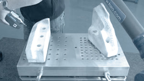
Digitizing processes are widely used in die manufacturing. The digitization of dies and die parts helps to prevent production outages due to wear or die breakage.
For example, 3D CAD surfaces for die inserts can be quickly and easily prepared and then manufactured based on digitized data (point clouds). The high accuracy ensures that the inserts can be exchanged without a renewed die tryout phase. In the same way, dies that have been through tryout can be digitized and ground component radii reverse engineered in the CAD data, for example.
Compensation measures can be defined and implemented in the individual component or in the assembly based on the digitized data with a target/actual comparison in the CAD/CAM process. This enables the effective and fast implementation of both dimensional corrections as well as surface optimizations. Changes to the die or various component conditions can be compared on screen. It can then be decided whether the changes should be implemented directly in the shop or in the design. The digitized data can be used 1:1 for preparing the correction data in design changes, ensuring a high degree of accuracy.
Digitizing also plays a role in the manufacturing process. Roughing in particular is still extremely time-intensive here. Casting models are prepared in die manufacturing, especially for large components. Problems arise when the cast components and designs do not match. A reliable and highly automated CAD/CAM process results if the cast components are digitized immediately on receipt. This also enables machining time to be reduced. Option: Digitization is also worthwhile for finish-machined die parts: In order to check correct functioning of the die, individual parts are digitized after machining and are virtually "assembled" in the CAD/CAM system and are checked for possible collisions. The dies are not released for assembly and tryout until any errors have been ruled out.
Tebis Process Solutions
Tebis enables efficient roughing based on digitized cast components. Efficient roughing is based on integrated technologies such as for full width avoidance, feed rate optimization and machine retracts optimized for the blanks as well as adaptive milling strategies. Option: Tebis exactly simulates the new HFC (High Feed Cutter) and HPC (High Performance Cutter) tool technologies, reducing machining time.
Accuracy and Perfect Quality in 3D-Surface Machining
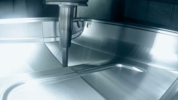
Tebis technologies such as constant 3D-path allocation and strategies for HSC point distribution enable perfect quality and reduce reworking on the die.
Hammer peening after milling reduces roughness and consolidates the surface. Highly-stressed radii, trim edges and restriking dies are generally hardened. Both process steps are fully integrated in Tebis.

Innovative Active Surface Process
Active surface creation plays a central role in the die manufacturing process. This step is critical to quality and dimensional accuracy of the sheet metal parts. FEM-based systems provide a highly accurate calculation of springback. A compensation strategy based on these results is determined as an overbend recommendation for all dies and is transferred to the Tebis CAD/CAM process in the form of point clouds. The simulation data, such as for structure parts can be used for overbending. The same applies for scanned sheets in hot forming processes, for example. Abstracted surface rules are especially useful for outer skin components, retaining the original curvatures of the class-A surfaces. Tebis provides class-A analysis functions as well as powerful surface optimization functions for early detection of errors in the visible surfaces of the components.
Tebis active surface preparation includes compensation of sheet metal thinning, incorporation of pressure surfaces and free design of negative radii. Specialized functions enable programming without virtual wall thicknesses, with the result that visible edges and steps in the die surface disappear. Compensation for press deflection and die deformation can be simply integrated with corresponding overbending rules.
The overall CAD/CAM process is simplified by programming on a surface instead of virtual wall thickness attributes. Working with Tebis templates enables a high degree of automation in NC programming and reduces programming time. Homogeneously prepared active surfaces form the basis for the use of HFC milling tools. Calculation times can also be reduced, especially for residual stock. Benefits in the spotting process: Reduced reworking on the die enables direct installation of the dies in the press.


