Call us:
+1-248-524-0430

-
Automation and standardization of processes
Large potential savings in single-part manufacturing
Simplifying CAD design and CAM programming and using templates for standardization are important steps along the path to full automation. But fully automated and safe process flows also have no alternative as the basic requirement for efficient, low-personnel manufacturing .
This requires that you store your manufacturing environment, your manufacturing knowledge and your manufacturing processes entirely in the digital world. Tebis 4.1 forms the basis for this.
Tebis 4.1 milestones for digitalization and automation
- MES ProLeiS
- Virtual clamping device library
- Process-integrated measurement
- Intelligent collision avoidance strategies
ProLeiS MES software fully integrated
Large savings can potentially be realized in single-part manufacturing thanks to standardized and stored manufacturing processes. This requires close intermeshing of CAD/CAM and MES technology.
With ProLeiS and Tebis 4.1, you can split up entire assemblies and individual parts into proven processing sequences. Even complex manufacturing projects can be planned, controlled and implemented. Logistics for purchased parts, blanks and machine components are also accounted for throughout the process. The key advantage: Your machines are optimally utilized and all activities can be assigned to specific manufacturing designers, NC programmers and machine operators.
ProLeiS MES can also be easily combined as an integration platform with upstream and downstream systems like PDM, ERP and machine control systems. CAD/CAM and MES technology closely intermeshed
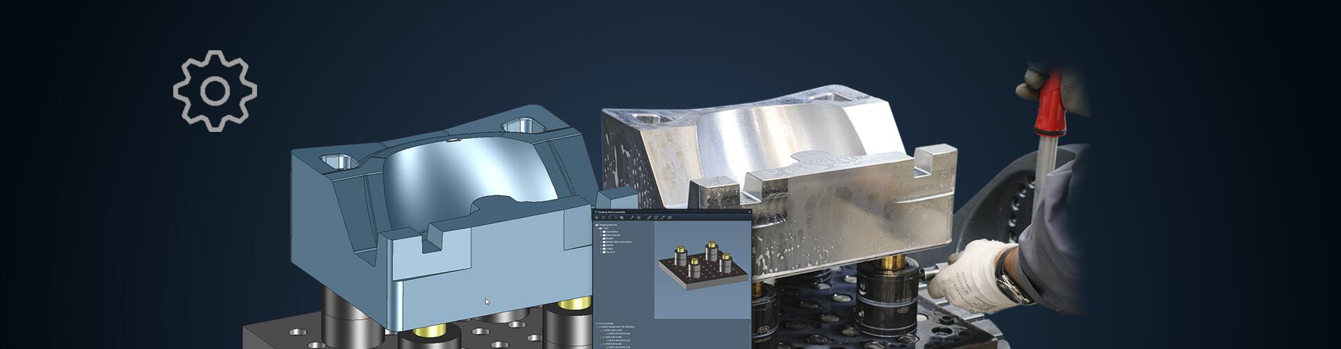
The clamping device library completes the virtual process libraries
Your benefits:- Create and manage clamping elements and clamping device assemblies
- Import and directly use external data such as clamping elements and products directly from the manufacturer via direct interfaces
- Quickly adapt clamping situation to the specific manufacturing task
- Simple positioning
- Automated plausibility checking
- Set up the machine one-to-one in the virtual world
- Simplified setup processes in production
Construct groups of clamping devices
You can manage all clamping elements and combine them in clamping device groups in the clamping device library. Using predefined connection points and an automatic filter function that only offers elements with appropriate connections, you can quickly and conveniently construct simple vises in the same way you create zero point clamping systems with a variety of clamping plate systems. Multiple setups are also integrated. If individual elements in a clamping device group can be physically moved, you can specify any necessary degrees of freedom to restrict the direction of movement.Virtual machine setup
You can use appropriate elements and configurations from the library for virtual setup. The setup process follows a logic similar to the assembly of clamping device groups:
Only clamping devices that fit on the selected machine are offered. You can also create the reference point when clamping. With just a few clicks, you can use connection points to position the clamping devices on the part and position the entire part on the machine table. The part, collision elements, clamping device groups and individual clamping elements can also be positioned independently.
The unique advantage: The result arrives at the setup station with no loss of information – because the NC output automatically generates precise and comprehensiveNC documentation. The person responsible for the setup can immediately see what needs to be done. Clear component designations show the clamping devices required, how many are needed and where they have to be positioned.Shorter setup and machining times with process-integrated measurement
Completely integrate your measuring tasks in the manufacturing process – easily and with reliable collision protection. For example, you can check to ensure that the part is correctly set up, the blank is correctly dimensioned and oriented and, after machining, that the part does not require any refinishing that would not otherwise be detected until after unclamping. All of the necessary functions are structured together – from probe calibration to point measurement, angle measurement based on points or circles, circle and rectangle measurement, to checking of grooves and ribs. Integrated tolerance testing can be performed to determine whether the order can continue to be machined or must be interrupted. This results in a reliable and highly automated process with combined milling, turning and measurement operations that prevent damage to tools and machines. This results in shorter setup and machining times, higher component quality and fewer correction grinding operations. You can benefit from these functions even on controls that don’t have their own measurement cycles.The machine head is fully accounted for in collision checking
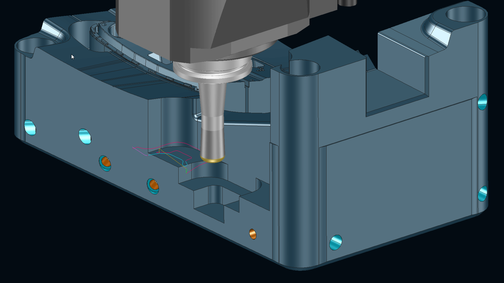
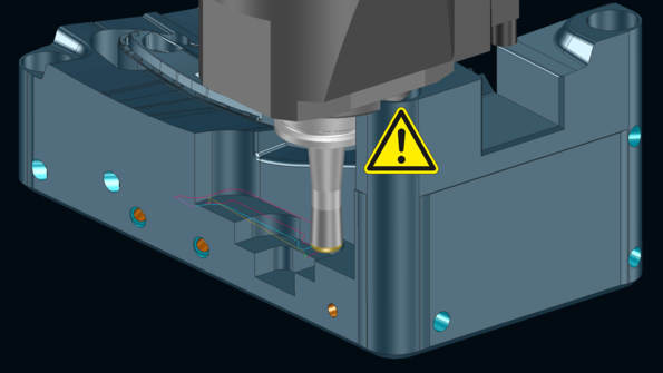
Quickly create collision-checked toolpaths: In the event of possible collisions with the machine head, milling areas are automatically reduced or are excluded from the machining operationin the NC calculation.
Your benefits:- Greater process safety
- Enormous time savings: Without automatic area reduction, you have to manually correct the collision after calculation and then recalculate the machining operation
- With area reduction, the shortest possible tools are used for every milling job, ensuring optimum cutting conditions
 Head collision without area reduction
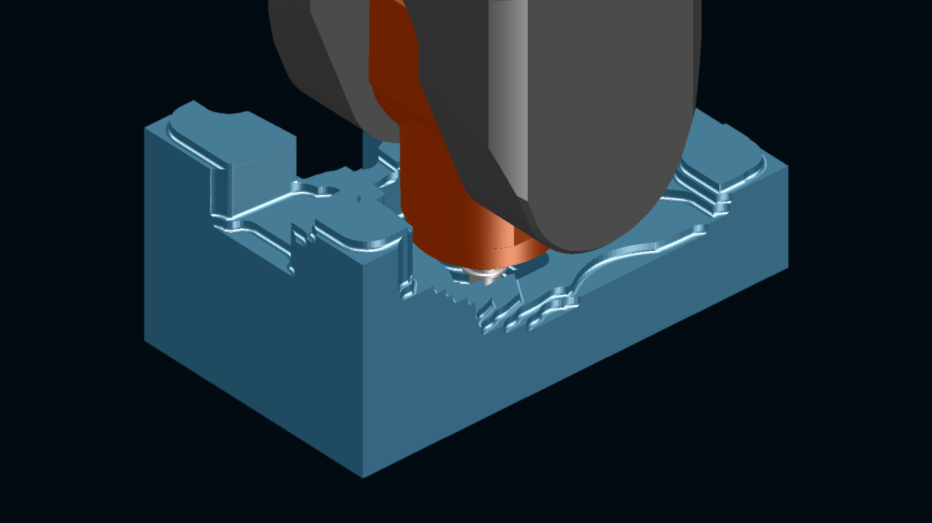
 Preventing head collision with automatic area reductionThe "Programming with virtual machine" license also enables interactive rotation of the head or table about the C axis in the machine kinematics. The benefit is especially clear for asymmetrical heads: The maximum possible material is removed with the selected tool. Unnecessary residual stock is avoided. The interactive rotations are immediately accounted for in the area reduction.
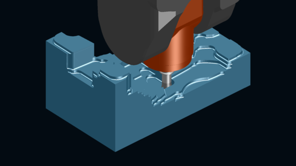 Maximum possible material removal with fixed C axis
 Significantly more material is removed with the C axis rotated