

-

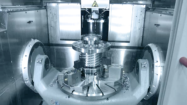
The Tebis Lathe module in use
Interview with Reiner Schmid, Tebis AG
Reiner Schmid is the Product Manager at Tebis AG for mechanical engineering with emphasis on virtual machines and turning. During the interview, he took a stand on turning processes with Tebis.
Tebis offers its customers an effective solution for turning. One major benefit is the ability to combine turning processes with drilling and milling operations into a complete machining operation. We talked with Reiner Schmid, Product Manager at Tebis AG who is responsible for mechanical engineering, about the strengths of the special Lathe package.
Mr. Schmid, what is the target group for the Tebis Lathe module?
We have not reinvented turning, but our software meets the high demands for accuracy in lathe machining. At the same time, it saves time during programming and manufacturing. Our options clearly target the areas of drive technology, hydraulics, motors and transmissions. These are areas covered by traditional mechanical engineering. The focus is on single-part manufacturing, but we also meet the requirements for batch production. Entrepreneurs who identify with this description and whose portfolios include complex, sophisticated components should take a closer look at the Tebis solution.
Should the lathe software be considered independent of the other manufacturing processes?
There are certainly purely turned components, but the major challenges always arise from combinations of turning, milling and drilling. When these manufacturing techniques work together, the power of Tebis becomes fully apparent.
Tebis knows how to make these combinations work for the customer. How should we visualize this?
First of all, only one NC program is created. The error rate is very low in comparison with individually programming the machining operations. If as many manufacturing steps as possible can be executed with a single setup, setup times are reduced, and the manufacturing accuracy increases because reclamping is not necessary. This is only possible when a single application handles all the programming. The process begins with low administrative effort. The tools used in all manufacturing methods are combined in a common library. This also applies to other functions like machining templates and machine models. This single-system strategy is characterized by familiar operation common to all functions. The programming processes are very similar, considering the various machining technologies used.
You mentioned a common tool management. But the geometry of turning tools is far more involved than the geometry of milling or drilling tools. How do you handle the tools?
With Tebis, tools play a decisive role in the calculation of NC programs. Any geometry can therefore be mapped. This includes all of the components of the tool – the insert and tool holder. This is the only way to avoid collisions. After the calculation, Tebis checks to see whether the tool would collide with the component or protected surfaces, and it automatically switches off any hazardous NC paths. We call this “area reduction.” The tools themselves can be designed as 3D data or, in the case of standard tools, directly entered with their ISO code.
Let’s stick to the tools, specifically tool changing.
The tool change process has a very high hazard potential in turning machines where the tools are often loaded in a turret. Don’t forget that, in addition to component and jaw chucks, other machine units have to be managed, controlled, and monitored: for example, steady rests and tailstocks.
If machines are equipped with a counter spindle, the individual work steps must be split accordingly. You keep mentioning complete machining. How do you implement this task?
Tebis generates a single NC program in this case as well. Front and rear are machined within a single machine run. The program is created from the individual NCJobs for each spindle, and the transfer parameters between main and counter spindle are also defined in this process.
Tebis uses a blank as the starting geometry. What is the blank used for, and how is it created?
On the one hand, the blank is used to prevent collisions during the calculation of NC paths, which is a purely mathematical reason. On the other hand, we are able to represent a material removal simulation and store the blank in different machining stages. This allows the milling machining to access the blank that has been previously turned, and vice versa. There are no limits on the transfer between different machining methods. The material removal simulation visually displays the current intermediate status that precisely matches the real machining situation at the machine. The blanks can be designed in the system itself, either by using comprehensive CAD functions, or by scanning and importing them via interfaces. In the latter case, they perfectly match the real situation.
A virtual machine for milling delivers maximum manufacturing reliability. Is this also possible for turning, and are the complex movements also safeguarded?
The virtual machine is an integral component of the Tebis CAM system. The machine type doesn’t matter, because all components are represented for all machine tools and are taken into account during programming. For example, the system looks for a tool change for all tools present in a turret, which may include a long drill right next to a plunge chisel. The previously mentioned component transfer between main and counter spindle is also taken into account and simulated. Only released movements are subsequently realized via the integrated postprocessor, in order to be precisely executed by the corresponding machine tool.
Another key issue: special applications.
It depends on the individual situation. Our main focus is certainly drilling, turning, and milling. The primary task for special applications is the integration into the manufacturing process. We have already realized some solutions with special tools for hobbing and broaching.
Accuracy is usually higher in turning compared to milling. How do you handle this?
When we program on 3D geometries, tolerance limits are usually not included. The solution is the Lathe Contour Preparation add-on, a fully parametric 2D drawing and dimensioning tool. Derived from 3D components, geometries can be precisely drawn and assigned a tolerance range. These data are then directly evaluated during programming in the job manager. By the way, this add-on is also outstanding for integrate standard geometries like undercuts according to DIN 509.
A software program is not static. What enhancements are planned for the future?
Tilted turning is already possible, but we still have quite a bit to do on simultaneous B-axis turning. Of course the future also holds multi-channel technology. The strategies for downward machining will also be enhanced.
Mr. Schmid, thank you for this conversation.
 Reiner Schmid, Head of Product Management at Tebis AG


